Jorie van Haren
Miss Silvia Pi
2022 – 2023: Rancilio Silvia Project

Date:
Summer 2023
Table of Content
Introduction
About one year ago I started thinking about my first foray into home espresso. After scouring the internet for a reasonably priced second-hand machine, I ended up with a Rancilio Silvia v2. The machine was fully working, had no rust, and best of all; could be had for the low price of €120,-. After taking it home I did what any sensible human being would do, I pulled one okayish shot (with coffee pre-grinded by Silvia’s previous owners), attempted to steam some milk – knowing everything worked – I immediately disassembled the machine.
Why a Silvia?
The Rancilio Silvia is – together with the Gaggia Classic – one of the easiest to work on espresso machines. Silvia’s are also by far the most modded machines, giving me plenty of reference materials to look at and take inspiration from. Additionally, when we move to any higher-grade machines, modding will result in less overall gain (and will become increasingly more scary).

In this blog I will take you through my journey of modding a Rancilio Silvia; finding random parts, figuring out ways to overcome nich problems and putting everything together. The whole project runs on a Raspberry Pi 4b, which I had conveniently laying around.
My eventual goal was to – on a tight budget – create a smart espresso machine capable of pulling some great shots. After completion, the machine should be able to automatically, with some degree of precision, replicate someone’s favourite shot.
Why would anyone want to automate the joys of this manual process?
While I may enjoy the whole process of manually weighing each shot of espresso and trying to time things just right, my S.O. just wants a good cup of coffee by pressing a single button. But no worries, I left all the original hardware buttons – I even added new ones for even more adjustable variables.
Before we start, here comes the obligatory warning that parts of this project deal with mains voltage. While wrongly connected sensors interfacing with a Raspberry Pi can probably only damage the Pi itself, mains voltage can very much ‘damage’ or even kill you. Please try at your own risk, and if you do decide to recreate parts of this project ALWAYS triple-check that the machine is fully unplugged from the wall. I am not an engineer or electrician, so this blog is meant for entertainment purposes only.
Stable Temperature Control
The single biggest downside of a Silvia is its poor temperature stability. The stock machine has a simple thermostat turning off a beefy heating element whenever it exceeds 95°c. In practice, this method of heating element control results in significant temperature fluctuations with temperature deltas of up to 15°c. One could decide to just live with this or use techniques like temperature surfing, where we try to pull our shot at just the right temperature. But honestly, for me, this sounds like a nightmare. I thus choose to implement what’s called PWM, PID control. Using a PID controller we can proportionally control power to the boiler based on its current temperature and its rate of change in temperature. There are many plug-and-play KITS available to give you this functionality without the need for heavy (manual) modding, but where is the fun in that…
The Silvia’s boiler is controlled by two thermostats wired in-series. The first thermostat is meant for brewing and turns off when it exceeds 95°C. The second thermostat, used for steaming, shuts down at 140°C. When we activate the steam switch, it bypasses the brew thermostat, making the power switching dependent solely on the steam thermostat. Since we primarily desire precise control over brew temperatures, I’ve opted to replace the brew thermostat with a zero-cross SSR (more on this in a bit). I will leave the steam thermostat connected in series. The steaming pressure and temperature are already perfectly acceptable for my purposes – I’m not that much of a milk drinker anyway. But maybe more important, an essential benefit of having the steam thermostat wired in series is that even when my code misbehaves or the SSR gets stuck in an on-state for whatever reason, the temperature within the boiler will never exceed 140°c.

PWM control, what is it and how does it work?
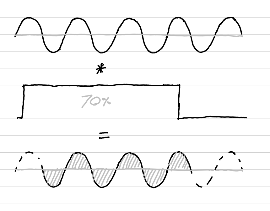
Pulse width modulation is a way of controlling the proportion of -on vs -off time of a pulse. A PWM duty cycle of 1 indicates a continuously high signal, while a duty cycle of 0.5 means the signal is on for half of the time followed by an off period for the other half. To achieve stable temperature control, I want to proportionally switch my 1100W heating element in many discrete steps. For Europe (where I’m located), the mains voltage is 230V and switches at 50Hz, meaning we have 100 half cycles where the main voltage crosses zero for each second.
By setting our PWM cycle length to 1Hz, we can effectively control the boiler in 100 distinct steps. The PWM value (0-100) corresponds to the number of half cycles we activate each second. For instance, a value of 23 will power the boiler for 23 half cycles, (about 230ms -on time each second), and remain unpowered for the remaining 77 cycles (about 770ms -off time each second).
Solid State Relays
In practice, we use a Zero-Cross Solid State Relay (SSR) to efficiently and quickly switch power based on our PWM controller. These SSRs are opto-isolated, making them a good choice for interfacing with the Raspberry PI. The DC-side of the SSR can be directly activated by a 3.3V logic output – the PWM signal – of the raspberry pi. The specific SSR model I used in this project is the Fotek SSR-40 DA. [Since many of the Fotek SSRs available nowadays seem to be fake knockoffs, I opted for the 40 amp version to ensure reliability – even though a 40 amp relay may seem excessive for a 1100W boiler at 230V].
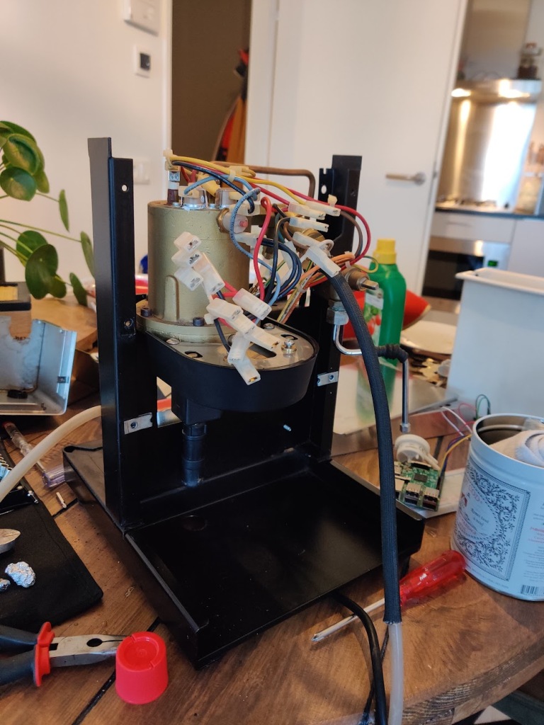
I securely mounted the SSR on the Silvia’s middle metal frame, applying thermal paste between the SSR’s backplate and the Silvia’s midplate to keep the SSR nice and cool.

Temperature Readings
To determine the proportional power for our PWM, we need a reliable temperature sensor with some specific capabilities. For our use case, the sensor should offer low-latency readouts, easy interfacing with a Raspberry Pi, sufficient resolution for precise boiler adjustments, and a suitable range covering room temperature, boiling water, and steaming temperatures (up to 140°C) without risking damage.
I opted for the TSIC 306, which conveniently interfaces with the Raspberry PI over a 1-wire bus. The sensor offers a resolution of 0.1°K and can handle temperatures ranging from -50°c all the way up to 150°c. An added advantage is the abundance of python-TSIC implementations available in the community, making the interface really straightforward. Ow, and not unimportant, they cost only ~€8,-.
To mount the sensor, I first removed the original brew thermostat, bend the little metal clip, and securely positioned my sensor – with some thermal isolation padding and thermal paste – flush against the boiler. All in all, this seems to work great, temperature readings seem very stable and coherent.
To test consistency, I placed a temperature probe beneath the shower screen and pulled some water, finding the temperature readings to be very similar. I did observe that the boiler’s temperature readings dropped faster compared to the actual temperature near the shower head.
This discrepancy can likely be attributed to the temperature sensor’s location, which is close to the water inlet of the boiler. As a result, when the pump is running, fresh cold water gets mixed disproportionately with the hot water at the top of the boiler. Fortunately, during slower shots, this disparity isn’t much of a problem; it merely implies that we can be slightly less aggressive with our PID tuning.


PID-Control
Now that we have our temperature readings and our SSR is set to proportionally switch our boiler, we can start coding a PID-Controller. This controller helps in regulating temperate by continuously adjusting the power output based on feedback from the temperature sensor. PID stands for Proportional, Integral, and Derivative, which are the three main components of this kind of controller.
The Proportional term calculates the difference between the desired setpoint and the actual temperature, while the Integral term accumulates past errors to make up for any steady-state errors. Additionally, the derivate term predicts future errors based on the current rate of change. Combining these three components, we can quickly and accurately guide our boiler to the desired temperate and keep it stable.
The output of the PID-Controller directly determines what the appropriate PWM duty cycle should be (0-100). Since our aim is to brew at 93°c, we can set our setpoint to 94°c (adding 1°c to compensate for temperature sensor placement). Next, we pull some shots while logging temperature over time, and begin tuning the three free parameters of the PID-Controller.
Our goal of this tuning process is to achieve stable temperatures throughout the shot, avoiding huge dips in temperature or big overshoots beyond our setpoint. While doing this tuning step I would advise keeping the heating light plugged in. If everything works as intended, the light should remain continuously on at lower temperatures, start flashing at higher temperatures, and mostly remains tuned off when near its setpoint. This visual feedback helps to ensure everything is working as intended.
Pump Control
Since the Silvia has a vibratory pump, controlling the output flow and pressure is far from a straightforward task. The thought of fitting a controllable rotary pump did briefly cross my mind. However, since we are on a budget, I decided against it. Besides, a pump upgrade mod is probably better suited for larger machines like a Profitec or Rocket.
If anyone has managed to implement such a modification successfully or has plans to do so, let me know! For now, we had to be creative with our pump control solutions.
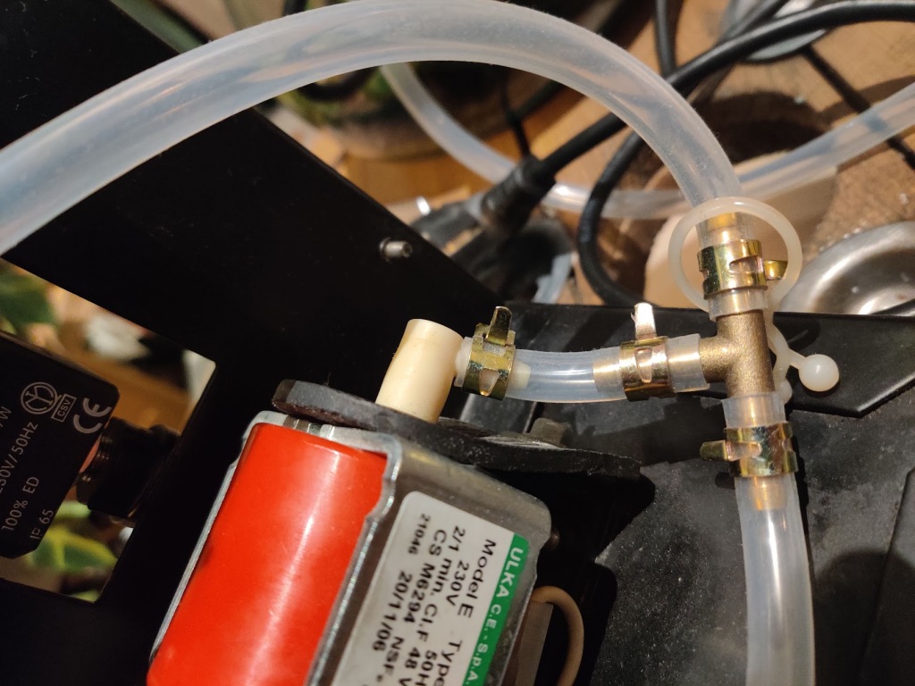
The type of vibratory pumps commonly used in nearly all cheaper home espresso machines (Ulka EX5) generate pressure by rapidly magnetically pushing and pulling a rod back and forth, forcing water through a check valve. Typically, these pumps produce pressures of 15 bar. Downstream in the loop, an overpressure valve is utilized to bleed away excess pressure (everything exceeding the set value of for example 9 bar).
The vibratory pump operates directly on mains voltage, and the output flow is contingent on the power grid’s frequency and voltage. To control the pump, we have several options:
- A. We could opt for a simple mechanical relay for basic on/off control. By using a double throw relay, we can even combine control of the 3-way solenoid and pump with a single relay.
- B. For a bit more control, we can utilize a random fire SSR to regulate the pump, akin to how a leading-edge or trailing-edge dimmer works. We know that this should work in principle (to some extent), as there are plenty of people using light dimmers to control their pumps. For a Raspberry Pi mod the method would be similar, but with digital control of the dimmer.
- C. The most effective option for controlling a vibratory pump is to use what’s known as an IGBT PWM. For a comprehensive explanation and implementation details, take a look at James’: Project Coffee: Es(pi)resso Machine project.
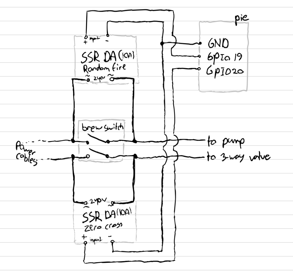
For me, option C was a bit too much, so I opted for the simpler but somewhat suboptimal option B. The idea is to cut the wave short at each half-wave, reducing the water pushed through the output. Unfortunately, the rod within the pump has some inertia, preventing us from setting the cutoff period to any value. At some values the electromagnet will not have enough power to move the rods within, resulting in a stall. Despite this limitation, we can still control the pump from a minimal pressure of around 3 bar up to 9 bar (anything higher will bleed out the OPV).
Normally, when using a random fire SSR, the lack of synchronization with the power grid phase can be a significant hurdle. Fortunately, there exist some really nice off-the-shelf solutions, saving us from the difficult task of synchronizing it ourselves. WaveShare offers the 2-CH TRIAT HAT, which is a dual-band AC dimmer that operates on the basis of phase cutting or phase angle control. The module is conveniently packaged in a HAT for the Raspberry PI and offers excellent documentation to get it up and running smoothly.

Note that if I were to attempt a flow/pressure profiling mod again, I would likely take a different approach. While my simple dimmer serves well enough for pre-infusing, for complete – ‘Decent like’ – pressure profiling we simply dont have enough control. As mentioned before, while we can adjust the waveform to a single degree, sadly, the electromagnets in the vibratory pump only respond at a certain minimum power. Moreover, since the vibratory pump builds pressure up to 15 bar, slightly reducing the pumps flow often results in just a slower ramp-up towards the OPV set pressure, especially when grinding very fine.
So, are there other potential solutions besides the ones mentioned earlier?
One alternative solution could be changing pump control to a simpler on/off relay and leaving flow control to a solenoid relay positioned near the original OPV. This solenoid relay would bleed off excess pressure to before the pump, similar to the OPV, but with the advantage of being digitally controllable. I have some ideas on how this could work, incorporating feedback loops from the digital pressure transducer and flow meter for full pressure and flow control. However, my machine is already cramped for space as it is, so I’ll leave this project for someone else to experiment with (or perhaps for my future self if curiosity gets the better of me).
Pressure Sensing
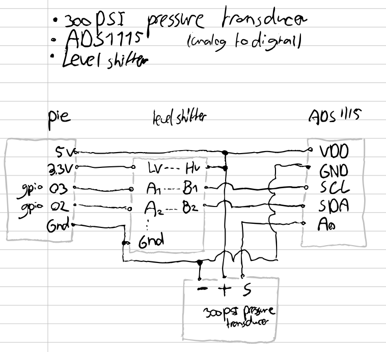
A smart espresso machine wouldn’t be complete without a way to measure pressure. Although an analog sensor would suffice for my needs, having only an analog gauge would be a waste of logging possibilities. Besides, maybe in the future I want to use the pressure value to influence the pump’s power through a feedback loop. Therefore, I decided to incorporate a pressure transducer and interface it with my Raspberry Pi.
As the Raspberry Pi can only read digital signals, and most pressure transducers produce analog voltages, we need to convert the signal using an ADC (analog-to-digital converter).
There are several potential locations to place our pressure transducer within the system. In theory, since this is a closed system, pressure readouts from all of these locations should be equal. However, since the system is leaky, readouts may vary in practice. The most accurate brew pressure readings probably would come from a transducer within the brew head, but unfortunately, this option is not feasible.
Instead, I chose to position my transducer between the OPV and the Boiler, which happens to be one of the easiest locations to fit it. All it takes is using a t-piece instead of the existing male-to-female piece. For this purpose, I used a brass f-f-m 1/4″ fitting. Other potential placements include just after the pump or somewhere along the copper tube leading to the steam valve.
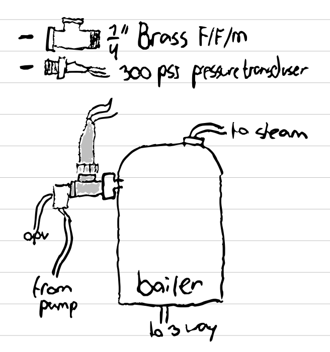

For the pressure transducer, I opted for a relatively generic one from Amazon. These transducers have a working range from 0 to 300 psi, equivalent to pressures between 0 and 20 bar. The (limited) documentation specifies an 0.5v output for 0psi and an 5v output for pressures of 300psi. Using this information and assuming linear behaviour, we can easily calculate the pressure corresponding to specific voltages.
PSI = 66.67 * ( V – 0.5 )
BAR = 4.5965 * ( V – 0.5 )
For the ADC I selected the Adafruit ADS1015, which created an I2C bus of – in my case – our single-ended input on channel 0. Using the adafruit_ads1x15.ads1015 module, we easily read the voltage and then translate it into the corresponding pressure value in bars.
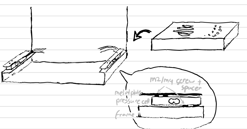
Driptray Scale
Upon coming across Raspberry Pi projects utilizing load cells for DIY digital scales, I decided to incorporate this feature into my setup as well. While the hardware modding was relatively straightforward, initially, interfacing the loadcells proved to be a bit finicky.
A load cell operates based on the relationship between force, material deformation, and the flow of electricity. In a nutshell; the electricity flow is directly proportional to the pressure on the cell. To interface with the load cell, we read values from a small module that serves as both an amplifier and ADC, the HX711.
In my initial approach, I connected the load cells to both the A and B sides of one single HX711. While this worked, I noticed a huge slowdown in readout speed compared to using only the A-side. While there are ways to potentially accelerate the readout speed on both A/B, I decided to address the issue differently. I opted to use two of these cell amplifiers, utilizing a total of 4 GPIO data pins. If you are running out of pins, check out ways of accelerating sampling rate on A/B, this will allow you to free up two pins (while still being able to sample at 10, or even 80hz).
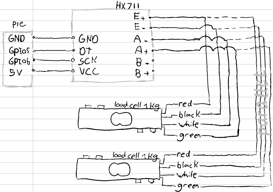
Initially, while testing the sensors, I was getting very noisy output. The reason for these issue was due to the connections not being securely soldered and a weak power supply on my Raspberry Pi. Readouts can be remarkably stable, but these boards, particularly on 3.3V, can be a bit finicky. Therefor, please make sure every cable is securely soldered to the ADC board.
For calibration, I simply removed the drip tray, and placed a known weight on either loadcell. Dividing the output value by the calibration value yielded an incredibly precise weight measurement. To obtain the total weight, I simply added the weights from both load cells together.

Flow Meter
While the drip-tray scale allows us to calculate the output flow (water + extracted coffee), I wanted to also add a flow meter. This addition would enable us to measure both the water input and the relative volume of water per second displaced (the flow rate). However, finding a suitable flow meter posed a bit of a challenge, as many commercially available options are expensive and often designed for larger volumes of water.
Luckily, the es(pi)resso project from James provided an excellent suggestion: the Digmesa FHKSC 932-9521/B flow meter. This flow meter is readily available and affordable as a spare part for many capsule machines. The concept is fairly simple – the flow meter is positioned between the pump and the water reservoir. It contains a basic dynamo, generating an electromagnetic pulse with each full rotation when water flows through it. All we need to do is count these pulses and correlate their quantity to the amount of water passing through. et voila; we have measured flow rate.


There are a few small hurdles to consider, particularly regarding how the flow meter registers backflow due to vibrations and the water return from the OPV directly to the water tank through one of the hoses. After conducting some tests, I found the most stable setup for me involved placing the flow meter between the water inlet and the pump. Then, I added a T-split fitting after the flow meter to (re)introduce the water from the OPV. This way the water counted by the flow meter matches the exact volume of the water that was consumed. As a result, we now have only one hose feeding into the water tank, with the water from the OPV feedback occurring after the flow meter.
Initially, I had the T-splitter and flow meter positioned very close to the actual pump, which caused a lot of noise in the pulsing signal. After some investigation, I discovered that the pump, especially at high pressures, was pulsing water back and forth inside the flow meter, resulting in numerous phantom pulses and inaccurate readings. To resolve this issue, I moved the T-splitter and flow meter a bit backward in the loop, effectively minimizing the noise and ensuring more accurate measurements.

Water Level Sensor
Now, let’s move into some of the fun side projects that, while not directly related to espresso making, add a nice touch to the setup. One of these mods is the water level sensor, for which I opted to use an ultrasonic sensor. One of the main advantages of such a sensor, instead of – for example – a floater, is that we can avoid having any electronics come into contact with the water.
The ultrasonic sensor operates similar to a car’s parking sensors. The sensor emits ultrasonic pulses and measures the time it takes for them to return after bouncing off a surface. Interfacing with the Raspberry Pi was a breeze, requiring only two GPIO pins, and one of many example modules to guide me.
Here’s how it works: we send an ultrasonic pulse from the sensor and note down the time. Subsequently, we wait and listen for the return of the soundwave, which happens when it has bounces at the air/water interface. We record the time once again at the time of arrival. Since we know the speed of sound, we can calculate the distance traveled. Distance (m) = known speed (m/s) * (time(s) / 2). The factor of 2 accounts for the two-way travel of the sound.
Using this distance measurement, we can easily convert it into a percentage volume within the water tank. A distance of 0cm from the ultrasonic sensor corresponds to 100% volume, while a measurement taken when the tank is empty gives us 0% volume.

Although this mod doesn’t directly impact the coffee-making process, it has been really nice to have. I usually display the water level on the top notification part of the screen, allowing me to check with a single glance whether it’s time to refill the tank or if I can go for another round. In the future, I plan to implement a popup in the middle of the screen to remind me to refill the tank, but that’s currently on the back burner.

E-Ink Display
To achieve a really unique aesthetic for my Silvia, I choose to go the E-ink route and fitted what essentially is a 4.2-inch Kindle to showcase all the information. I’ve always loved the look of these displays, with their reflective lighting offering a printed-out feel rather than a traditional lit-up screen. However, for those considering this route, these screens are not without their drawbacks. The screens are relatively slow to update; my Waveshare 4.2-inch model, out of the box, takes around 2 seconds to do a full refresh. While there are some hacks to speed them up, they aren’t always foolproof.
The screen operates using magnetic sign waves to precisely manipulate black and white blobs of ink. In the standard full refresh approach, we send a negative of the current image, followed by a fully black and fully white screen before displaying the desired image on a clean slate. While this approach minimizes short-term ghosting and excessive static magnetization of the particles, it is far from suitable for an interactive UI. For this reason we carefully altered the firmware to make partial refreshes possible. Where the full refreshes still take about 2 seconds to complete, the partial refreshes can be done in about 100ms, much better!
For the main interactive UI, I decided to update the screen only when there’s a significant change compared to the previous display or whenever we turn the rotary dial. Additionally, the main menu is presented in two modes, black-on-white and white-on-black, switching mode every 5 minutes. This approach should address the static problem whiles displaying images and allows for quick image updates.
Additionally, after 15 minutes of inactivity, the screen undergoes a few black/white cycles before entering deep sleep mode. This effectively clears any residual static from the screen, ensuring it is ready for use again the next time it’s activated.


For the user interface, I decided to include a notification bar, a main information display, and a selection of programs section. The notification bar provides real-time updates on the water flow and the remaining volume in the reservoir. In the main information section, you can view the tared weight on the drip-tray scale, the current boiler pressure, and the boiler temperature.
As for the selectable programs, they are represented by a set of icons, including americano water, tea water, single shot, double shot, and settings. Using the rotary selector button, you can easily navigate between programs, while pressing the rotary selector executes the chosen program – more details on this later.

Work in progress: I’ve also begun working on live graphs for each shot. The concept behind these graphs is to display the cumulative weight, flow, temperature, and pressure over time, providing some stats to play with. The ultimate goal is to use this data to easily replicate a flow and temperature pattern, all with the simple press of a button.

Physical Buttons
- Standby Switch
- Preinfuse Switch
- Rotary Encoder
For my switches, I chose to go for retro-looking, very clicky, rocker switches (double pole). Most of these switches are direct replacements for Silvia’s native switches, functioning exactly as before. I did change the behaviour of the power button. By shorting this button’s cables, I put the machine in a default standby state. Since I removed the brew thermostat and replaced it with an SSR, the system won’t start heating until we power the DC side of the SSR. This enables us to turn the system on and off at specific times of the day, such as in the morning, which can be controlled remotely. The new power button, which always springs back, simply toggles the standby script, controlling the screen and boiler threads respectively.
Additionally, I incorporated a pre-infusing switch, which activates the pump at a much lower pressure/flow rate (around 3 bar) for pre-infusion. When we switch the pre-infusion mode off, aside from stopping the pump, we can keep the 3-way valve open for a litle while, allowing for a blooming phase without losing pressure within the basket. Unlike the power switch, the pre-infusion switch is not springy, so you can toggle pre-infusion -on and -off as needed.

Last but certainly not least, the GUI can be navigated using a rotary encoder. Turning it clockwise moves the program selector to the right, and turning it counter-clockwise moves the program selector to the left. When you wish to run a program, simply press the rotary encoder.
While your rotary encoder might be more stable and easier to control compared to mine, mine required a bit of funnessing. The principle of a rotary encoder is simple: whenever we turn the encoder, its contact points make and release contact with a grounded gear, resulting in low and high signals. For a full clockwise rotation click, the expected behavior for the two pins would be:
| DT-Pin | CLK-Pin |
| 1 | 1 |
| 1 | 0 |
| 0 | 0 |
| 0 | 1 |
| 1 | 1 |
In a zero noise condition, one might get away with checking only parts of this sequence. However, even after debouncing the signal, mine only worked stably when I checked for the full sequence. Thankfully, implementing this full sequence check is still quite straightforward.
Wrapping The Machine
My poor-mans attempt of angle grinding a square to fit the screen in the machine left a few scratches, and despite my efforts to buff them out, the machine still appeared slightly scuffed. Before starting this project, I had the idea to vinyl wrap the machine and give it a retro look to complement the screen and clicky switches. However, I was hesitant about how it would turn out. Fortunately, the scratches pushed me to take the plunge, and I went ahead with it. I purchased some affordable ‘car grade’ vinyl on Aliexpress, costing around 10 euros.
Applying the vinyl was a straightforward process: I thoroughly cleaned the machine, slowly applied the vinyl while using a hair dryer to apply heat. Once the machine was wrapped, I reattached all the nameplates and plastic parts using 3mm steel wire clamps. To achieve a clean finish, I carefully removed any excess wrap with a sharp exacto knife.


Insulating The Boiler
As I chose the unorthodox approach of fitting all electronics within Silvia’s housing, I needed to insulate the boiler. This ensures that heat only travels upwards and doesn’t affect the E-Inks display, Raspberry Pi, and other components. To achieve this, I ordered espresso insulation foam and used long zip ties to securely surround the boiler. I also added some insulation on the top of my group head. All in all, I’m very happy with the results, during normal operation the raspberry pi never exceeds 50c.

Steam Wand Upgrade
My version of the Silvia is one of the older ones without the upgraded balljoint steam wand. While I don’t steam milk very often, having this upgrade would still be a nice addition. Instead of replacing the entire steam valve assembly, I decided to adapt the ball steam wand to fit the old assembly. When disassembling Miss Silvia, I noticed that most parts are standard-sized, giving us a good chance of finding an adapter that fits without taking up too much space.
The V1 steam valve housing requires an 8m thread, while the new balljoint steam wand needs a 3/8 thread. Although a bit tricky to find, I managed to get one from Aliexpress for a few euros. To try this upgrade yourself, you’ll need a brass hex nipple fitting with a 3/8 BSP male to 8m male thread (be careful not to mistake a 1/8 fitting for an 8m fitting, as they have slightly different thread sizes). The whole upgrade cost me around 20 euros, including the steam wand itself, the spring, an o-ring, a Teflon ring, the spring housing, and some food/heat-safe lube. An easier option would be to buy the full steam wand assembly, including the wand, but it’s slightly more expensive at around 65 euros.
Other information
You can find all the code I programmed and used for this project on my personal GitHub page: [will place in a week or so]
I want to emphasize that I created this project purely for my own entertainment, and that may be evident in the code. While I did annotate most of the code for my own documentation, please use it at your own risk. If anything is unclear, feel free to send me a message, and I’ll be glad to help out if possible and not too time-consuming. The same goes for the electrical modding; I’m not an engineer, and while I believe I have a good grasp of the basics to wire components to the Raspberry Pi, some wiring may be suboptimal or even incorrect. The provided wiring diagrams (if you can call them that) are up to date, but they are more akin to scribbles for my own understanding of how things are interfaced. Always double-check with other sources and do your own research/calculations.
This project was a lot of fun, and if any of you have suggestions for another coffee-related project, please let me know. For now, I’ll continue working on the software for this project. My TODO list includes implementing live plotting (nearly finished) and creating a feature to replicate a favorite shot based on a learned profile. As for the hardware side of things, I might not work on the machine for a while, as it’s now my daily coffee brewer.
Thank you very much for taking the time to read through my journey, and I hope you found it entertaining and inspiring.
Main Credits:
James’ Pispresso project: this project served as a huge inspiration for me. If you’re interested in (re)implementing anything, I highly recommend taking a look at his blog/code. Nearly all of his work is done in C#, and is coded very efficiently, so if you’re less into Python his project would be a good foundation to build upon.
Ben Krasnow’s video on E-paper hacking: Much of the process of hacking and fine-tuning the firmware for the Waveshare E-Ink displays was inspired by a video I stumbled upon, where the same display was used. The creator of the video also offers C# code that allows for partial and fast updates of these E-ink displays, which was incredibly helpful in my project.
Donate
or:
